This report is an overview on what is EMF (electromagnetic fields), what are the sources, how do we test for EMF, what do the measured values mean and what are the recommendations from governmental agencies.
Introduction
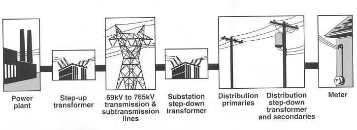
Without electricity, our world would stop. Electricity has great benefits and makes our lives so much more convenient. The electrical power system produces the lighting, heating, cooling and power we all need for our appliances and electronic devices. Electrical power distribution systems use alternating currents (AC) to provide electricity to residential, commercial and institutional buildings. The current is generated in power stations, transformed to specific voltages, transported via transmission and distribution lines and building wiring to the user. Step down transformers provide the required voltage and bring the three phase electricity to one phase currents which our internal wiring systems can utilize.
Power Frequency
Frequency is the number of occurrences of a repeating event per unit time. For example, if our heart rate is 80 beats per minute, the frequency is 80 per minute. In electromagnetics, we use the unit of hertz (Hz).
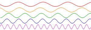
One (1) hertz is one repetition of the sinusoidal wave per second. The frequency (f) is the frequency in hertz (Hz), meaning the number of cycles per second. One hertz simply means “one cycle per second”. 100Hz means “one hundred cycles per second”. The
power line frequency is the frequency of the oscillations of alternating current (AC) in an electric power grid transmitted from a power plant to the end-user.
In our power system, the electrical current changes its polarity from positive to negative and back to positive sixty times per second or 60 Hertz. In most parts of the world the power frequency is 50 Hz, although in the Americas it is typically 60Hz. The electrical system in airplanes uses a 400Hz frequency.
Electric and Magnetic Fields
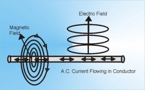 Conductors are wires which transport the electrical current. Electrical power systems generate magnetic and electric fields extending from the conductors. Magnetic fields are produced by the current flow in a conductor. Electric fields are produced by the voltage present on a conductor even without a current flow. The AC magnetic field is scientifically referred to as the magnetic flux density and is measured in units of milliGauss (mG) in the United States and in Tesla (T) in Europe. Electric fields are measured in units of Volts per meter (V/m).
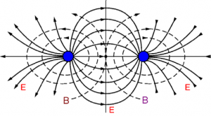 Magnetic fields are relatively easily measured with direct reading instruments. Magnetic fields extend in a quasi concentric circular pattern from the conductor (wire). Electric fields are significantly more difficult to measure. The field emitted from the source wants to reach the ground. The person conducting the measurements becomes part of this pathway and alters the electric field lines and results.
Almost all of the research, health effects studies, power design guidelines and EMF reduction methods common in the U.S. only address the magnetic component. In Europe and in the computer chip manufacturing and assembly industries, electric fields are an important component of field management.
 The terms “line” and “point” sources are used to define the sources for the magnetic fields. Line sources are transmission and distribution lines, electrical feeders and internal building wiring systems. Point sources are electrical transformers and motors. In a point source the conductors (wires) are wound up to create a coil.
The magnetic flux density is commonly referred to as magnetic field levels or EMF levels. We will use these terms interchangeably.
The magnetic flux density at any location is a result of the interaction of the following factors:
Distance to the field source (conductor)
Current flow “load on the line”
Distance between the conductors (lines, wires)
All factors being equal, the higher the current flow, the higher the magnetic field. This is a linear correlation. The further one moves away from any source the lower the magnetic field.
The magnetic field level in the space between separated conductors is much higher than the field on either side of these conductors. When such conductors are relocated to be directly next to one another (as in a cable), the surrounding field drops dramatically because the opposite but equal fields nearly cancel each other. Opposite and equal fields cancel themselves out. The distance between the conductors in a circuit is usually unimportant in internal building wiring, but is very significant for power transmission and distributions lines due to the large distance between the conductors.
AC Magnetic Fields
|
AC Electric Fields
|
Measured in milliGauss (mG), nT, µT, A/m
|
V/m, kV/m
|
Magnetic fields are created by current flow.
|
Electric fields are created by the voltage present.
|
Magnetic fields penetrate buildings and bodies.
|
Electric fields are directed towards the ground.
|
Background in nature is zero (0) mG
| |
H or B field
|
E -field
|
Measuring Magnetic Fields
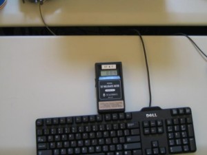
The magnetic flux density (EMF levels) can be measured with direct reading instruments. A direct reading measurement at one point in time at one location is referred to as a spot measurement. Due to the inherent fluctuation in the power supply on transmission and distribution lines EMF levels will change over time. To assess these fluctuations, data logging devices are used to obtain long-term measurement data.
|
Single Conductor
|
Fields decrease with the inverse of the distance
|
|
Multiple Conductors
|
Fields decrease with the square of the distance
|
|
Coils and Loops
|
Fields decrease with the cube of the distance
|
Furthermore, data logging can provide information on the maximum, minimum and average field strength present at a location. This may provide useful information when trouble shooting for sources of high magnetic field levels.


Coils are used to measure the magnetic flux density. The magnetic field induces a current flow in the coil which is measured and calibrated to express the magnetic field strength. Since magnetic fields are directional, the coil needs to be oriented in space so that the magnetic field lines flow through the center of the coil. An instrument with a single coil is referred to as a single axis meter. It needs to be oriented around the x, y and z axis in space to obtain the maximum field strength reading. This can be cumbersome and time consuming. Therefore, today’s professional instruments contain three coils to measure the three axes at the same time and provide a measurement result without having to rotate the instrument. Single axis measurements are the tool of choice when trying to determine the EMF source. A professional instrument with a 3 axis sensor array should also have linear frequency response. That means that the
EMF testing instrument measures correctly at different frequencies, such as frequencies between 30 -2000 Hz. The following formula is used to ascertain the actual magnetic field level of the different coils (x, y, and z).

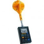
This calculation is performed electronically internal inside the instrument. Consumer instruments may not have a linear frequency response, resulting in erroneous results when other 60 Hz frequency fields are present.
Measurements should be conducted at the outside of the building or structure to obtain ambient back ground levels. We conduct measurements at all for corners of the property. Secondly, we circle the building identifying pot spots such as power feeds into the building, step down transformers and service drops (circuit breaker box). EMF levels inside at room or area are commonly recorded at its central location in the room. However, surveys should include a sweep through the room, its floor, ceilings and wall. This can identify underline wiring errors causing elevated magnetic fields.
Magnetic Field Monitoring Results in mG
|
Location
|
Minimum
|
Maximum
|
Average
|
95%
|
50%
|
John Doe Property
|
2.9
|
21.5
|
12.1
|
14.7
|
7.7
|
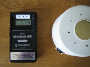 High field next to an air filtration device High field next to an air filtration device |
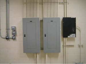 Service drops will create high field on opposing wall Service drops will create high field on opposing wall |
EMF REFERENCE EXPOSURE GUIDELINES
There are currently no Permissible Exposure Limits (PEL) for EMF levels published by the Occupational Safety and Health Administration (OSHA) or the EPA. Therefore, we are providing you with a chart of reference data of published studies, national and international suggested guidelines, recommendations by unions, working groups or governmental entities.
Table 1: EMF Reference Data in milliGauss (mG)
Power Lines and EMF levels
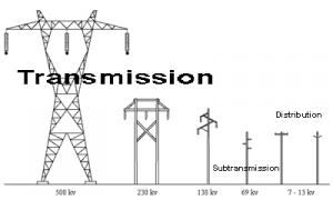 Electrical transmission lines create magnetic fields due to current flow and electric fields due to the voltage present. Power lines usually create relatively high magnetic field levels. This is related to the fact that the conductors (wires) are separated by large distances and therefore largely eliminating the cancelation effect of opposite and equal forces. Furthermore, large current flow contributes to the large magnetic flux density.
The power distribution system is divided into transmission lines, sub-transmission lines and distribution lines. The voltages on these lines are different. This voltage is reduced by step down transformers in substations. The following are the most common voltages present on power lines:
Levels
|
Source
|
1000 mG
|
World Health Organization (WHO) and International Radiation Protection Agency (IRPA)
|
1000 mG
|
American Conference of Governmental Industrial Hygienists (ACGIH) for industrial workplaces
|
<4.0 mG
|
International Agency for Research on Cancer (IARC) 2001
|
<2.5 mG
|
MPR 2 Swedish governmental standard for acceptable magnetic field emission for computer operator
|
<2.0 mG
|
TCO – Swedish labor union standard for acceptable magnetic field emission for computer operator
|
<2.0 mG
|
BioInitiative Report – Commercial buildings – EMF Working Group (US)
|
1.25 mG
|
Average EMF levels in US schools (L. Zaffanella study, 1998)
|
1.25 mG
|
California Department of Education’s (CDE) design goal for new school construction not to exceed 1.2 milliGauss
|
<1.0 mG
|
National Institute of Building Sciences (NIBS) 2006 – Precautionary Principle
|
<1.0 mG
|
BioInitiative Report – Residential environments – EMF Working Group (US)
|
0.9 mG
|
Average background level in residential buildings in a nationwide residential measurement survey of 1000 US homes (Luciano Zaffanella, 1994). Includes homes next to power lines and with wiring problems.
|
0.1-0.5 mG
|
Common background levels in residential not close to power lines and without wiring problems causing high fields (ET&T data)
|
 Utility transmission lines carry three (3) electrical conductors (wires) for each circuit. Therefore, it is referred to as a 3-phase circuit. The configuration of the individual conductors on the towers has a significant effect on the strength of the resulting magnetic field.
In the graphs, we compare the most common conductor arrangement with the low EMF conductor configuration. The three different phases are depicted by the colors of blue, yellow and red. The most common configuration is termed “Untransposed” and the low EMF configuration as “Transposed”.
The second graph shows to more rapid drop off in the magnetic field levels in the transposed configuration. An optimized wire configuration creates the lowest magnetic field levels.
Power Line Set Back Requirements
Since 2004, the California Department of Education (CDE) as part of the California Code of Regulations, Title 5, Section 14010(c) implemented setbacks requirements from power line easements for new school construction. The California Department of Education (CDE) had a design goal that AC magnetic field levels in new construction school environments are not to exceed 1.2 milliGauss (Zaffanella study 1998).
The following set backs are required:
100 feet for 50-133kV line (interpreted by CDE up to <200kV)
150 feet for 220-230 kV line
350 feet for 500-550 kV line
Exemptions are permissible if areas close to the power lines are used for parking areas and green belts.
Net Currents
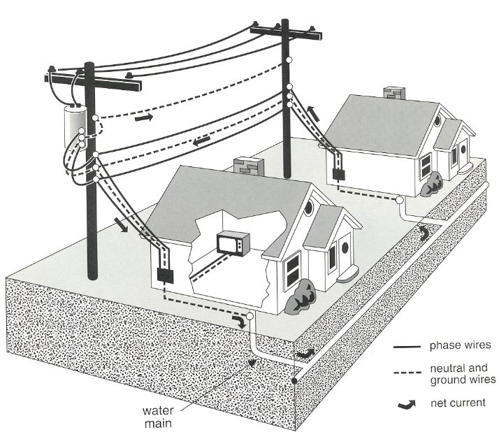
At point sources, such as motors and transformers the EMF fields are very high its proximity. However, the field drops off very rapidly with distance, within 3 – 5 feet to back ground levels. In building wiring systems, the “hot and “neutral” conductor should be positioned right next to each other and have the same current load. Therefore, the magnetic field is relatively and drops off rapidly.
In a Net Current or stray current situation, the hot and natural conductors are physically separated or have different current load condition. This causes current to travel an alternative pathway on other conductive materials. The magnetic field significantly increases around a single conductor or wire with a net current. If current flows on the grounding system, water pipes, and metal structural components such as beams, studs, and drop ceiling rails or a net current is present, the magnetic field can extend far into a building space. Net currents in wiring systems are a significant cause of elevated magnetic fields and are affecting large areas in buildings.
EMF Health Effects Research
EMF issues have reached a high level of concern among the general public and workers. This needs to be addressed at the international level since the problem is truly global in nature. Research objectives are needed with a clear focus on improving our database of scientific information used for health risk assessments.
EMF Health Summary
Scientific studies have been conducted for about 30 year.
Adverse health effects are still controversial.
-
Childhood leukemia
Lymphoma
Brain tumors
Breast cancer
Most entities call for Prudent Avoidance

1979, serious research about
electromagnetic fields (EMF) and potential adverse health effects started with the publication of a study by Mrs. Nancy Wertheimer and Mr. Ed Leeper. Their epidemiological study was conducted in the Denver area and reported a higher occurrence of childhood cancer in residences located near high voltage power lines and step down transformers. The study was based on visual observations and distances but without measurements for EMF levels. Positive health effects of electromagnetic field are well known in the medical field for bone healing.
In the 1980’s and 90’s, a flurry of studies followed without providing a clear and unequivocal answer. Sparked by increasing public concerns, devaluation of homes near power lines, and litigation cases, the EMF issue was temporarily put to rest by a public announcement by three Nobel Laureates stating that there are no possible causative mechanisms for these alleged adverse health effects.
In 1990, the EPA produced a report entitled “Evaluation of the Potential Carcinogenicity of Electromagnetic Fields.” which was released only in draft form and was withdrawn under some controversy as it classified EMF exposure as a potential human carcinogen. Another report, requested by the White House Office of Science and Technology Policy, produced by the Committee on Interagency Radiation Research and Policy Coordination (CIRRPC) of Oak Ridge Associated Universities, reached the opposite conclusion. This report, released in 1992, found no convincing evidence of health hazards from electromagnetic fields.
In 1991, Congress asked the National Academy of Sciences to review the available literature and provide information on the possible biological effects of EMFs and to perform a risk assessment. In 1996, the National Academy of Sciences report was released. It concluded that the current body of scientific data is insufficient to show that exposure to electromagnetic fields constitute a health hazard, primarily because no mechanism of action has been identified. However, the report recognizes that a clear association exists between residences near certain types of power lines and the incidence of childhood leukemia, although fields from the lines cannot be proven as the cause.
In late 1992 a
widely reported Swedish study (Feychting & Ahlbom) demonstrated a statistically significant association between EMF radiation exposure & certain types of cancers. The study found that
“children exposed to average fields of 3 mG or more in their homes had close to four times the expected rate of leukemia.” This was the first study that showed correlation of a dose-response gradient with the number of cases of childhood leukemia increasing in the presence of presumed higher exposure categories.

In 1992, Congress, as a part of the Energy Policy Act of 1992, mandated a $65 million, five year study to determine if exposure to low level, low frequency electromagnetic fields is detrimental to health and if so, to provide an assessment of risk. This full funding was never forthcoming. The Department of Energy (DOE) and the National Institute of Environmental Health Sciences (NIEHS) were charged with directing this research. Most of the work is known as the Research and Public Information Dissemination (RAPID) Program.

In 1993, the California Public Utilities Commission (CPUC) Decision 93-11-013 created the
California Electric and Magnetic Fields (EMF) Program to research and provide education and technical assistance on the possible health effects of exposure to electric and magnetic fields from power lines and other uses of electricity. This program was funded by money provided by the state’s investor-owned utilities, and is based in the California Department of Health Services (CDHS). A number of studies on health effect related to magnetic fields were conducted.
In 1996, the International EMF Project was established by the World Health Organization (WHO) to provide a forum for a coordinated international response to health concerns raised by exposure to electromagnetic fields (EMF).
In 1999, NIESH issued the final report on the EMF RAPID program.
In 2002, the International Agency for Research on Cancer (IARC) classifies ELF (extremely low frequency) magnetic fields as “possibly carcinogenic to humans”). EMFs were identified as a potential risk factor for breast cancer. Since 1987 evidence has been rapidly growing indicating an association between magnetic field exposure and breast cancer with a plausible mechanism via modulation of melatonin. An association between cancers and EMF exposure has been reported in over 110 epidemiological studies. However, follow-up studies were not able to replicate these results.
In 2007, The BioInitiative Report was published by the BioInitiative Working Group. This working group is comprised of international scientists, researchers and public health policy professionals. They conducted a comprehensive meta-analysis of existing research and found a significant number of studies have shown potential EMF associated health effects such as increased and altered cell proliferation, influences on hormones, heart, circulatory, and nervous systems. Reported symptoms range from irritability, insomnia, heart palpitations, and arrhythmia. This raises serious concerns about the safety of existing public regulations that limit how much EMF is allowable from power lines, cell phones, and many other sources of
EMF exposure in daily life.
Quotes From Selected Studies
The quotes selected in the report are not representative of the entire findings of the studies. For more information on these studies, please follow the provided links.
World Health Organization (WHO)
“
Reports were first published in 1979 that childhood cancer might be associated with exposures to residential ELF (extremely low frequency) fields. Numerous studies in many countries have been undertaken since then of possible increased cancer risks in children and adults from ELF magnetic field exposures. Special attention has focused on leukemia and on brain tumors, which early reports had suggested might be increased.
“ IARC has now concluded that ELF magnetic fields are possibly carcinogenic to humans, based on consistent statistical associations of high level residential magnetic fields with a doubling of risk of childhood leukemia. Children who are exposed to residential ELF magnetic fields less than 0.4 microTesla (4 mG) have no increased risk for leukemia. Because of insufficient data, static magnetic fields and static and extremely low frequency electric fields could not be classified as to carcinogenic risk to humans.”
CDHS – California Electric and Magnetic Fields Program
”
First, these studies do not show a clear pattern of health hazards. Some but not all animal and cell studies have shown biological changes linked with magnetic field exposure. However, it is not clear whether these biological changes would be the same in humans. Second, it is not clear which component (frequency, strength, harmonics, etc.) of magnetic field exposure might be hazardous.” “
Concern about possible health hazards from electric power use is supported by results of some scientific studies, but the evidence they provide is still incomplete and inconclusive and even, in some cases, contradictory. A good deal of research is underway to help resolve these questions and uncertainties.”
“
Most but not all epidemiological studies show an association between leukemia (a type of cancer) and an “indirect” estimate of high magnetic field exposure such as living very near a type of powerline that could cause of high magnetic fields or working where there is high electrical exposure. These estimates may not really represent a person’s true exposure at the critical time period when they may have started developing an illness. Also, these studies show that some estimates of magnetic field exposure might be related to cancer, but this does not necessarily mean that magnetic fields cause cancer. Indirect ways of estimating exposure may unintentionally include other risk factors like chemicals used at work or living in a particular neighborhood.” http://www.ehib.org/emf/shortfactsheet.PDF
NIEHS – EMF RAPID Report
“
The scientific evidence suggesting ELF-EMF exposures pose any health risks is weak” “Although each of these studies has its limitations, the limitations are different across studies, as are the designs and exposure assessment methods. Taken together, the studies suggest an association between exposure to magnetic fields and brain cancer, although the results are somewhat inconsistent.” “Although each of these studies has its limitations, the limitations are different across studies, as are the designs and exposure assessment methods. Taken together, the studies of incidence suggest an association between exposure to magnetic fields and chronic lymphocytic leukemia (CLL). “ “
The NIEHS concludes that ELF-EMF cannot be recognized as entirely safe because of weak scientific evidence may pose a leukemia hazard.” “
The NIEHS suggests that the level and strength of evidence supporting ELF-EMF exposure as a human health hazard. Are insufficient to warrant aggressive regulatory actions; thus, we do not recommend actions such as stringent standards on electric appliances and national program to bury all transmission and distribution lines. Instead, the evidence suggests passive measures such as a continued emphasis on educating both the public and the regulated community on means aimed at reducing exposures.”
Bioinitiative Report
“New regulatory limits for ELF are warranted. ELF limits should be set below those exposure levels that have been linked in childhood leukemia studies to increased risk of disease, plus an additional safety factor. It is no longer acceptable to build new power lines and electrical facilities that place people in ELF environments that have been determined to be risky (at levels generally at 2 mG and above).
“While new ELF limits are being developed and implemented, a reasonable approach would be a 1 mG planning limit for habitable space adjacent to all new or upgraded power lines and a 2 mG limit for all other new construction, It is also recommended for that a 1 mG limit be established for existing habitable space for children and/or women who are pregnant . This recommendation is based on the assumption that a higher burden of protection is required for children who cannot protect themselves, and who are at risk for childhood leukemia at rates that are traditionally high enough to trigger regulatory action. This situation in particular warrants extending the 1 mG limit to existing occupied space. “Establish” in this case probably means formal public advisories from relevant health agencies.”
“This report stands as a wake-up call that long-term exposure to some kinds of EMF may cause serious health effects. Good public health planning is needed now to prevent cancers and neurological diseases linked to exposure to power lines and other sources of EMF. We need to educate people and our decision-makers that, business as usual, is unacceptable” states public health expert and co-editor of the report, Dr. David Carpenter, Director, Institute for Health and the Environment at the University of Albany, New York.
After many decades of scientific research, the controversy about potential health effect still exists. The Occupational Safety and Health Administration (OSHA) has not established permissible exposure limits (PEL) for work places. However, a number of scientific studies and professional organizations advocate the principle of prudent avoidance and some have recommended guideline values. See the next section Reference Data.
Examples of proposed exposure metrics include: the average field intensity over a period of time, time spent in the field over some threshold value, field variability, the presence of switching transients on the field waveform, time in the day-night cycle when exposure is received, and the strength and direction of the earth’s geomagnetic field in relation to the power frequency field. Until the mechanisms by which electromagnetic fields interact with biologic systems are better understood, these questions cannot be answered, and a fully valid risk assessment will not be possible.
Conversion Tables
The following are conversions for commonly used measurement units.
Transmission Lines
|
220kV and 500kV
|
Sub-Transmission Lines
|
66kV and 115kV
|
Distribution Lines
|
4kV, 12kV, 16kV and 33kV
|
Secondary Lines
|
120, 240, 208 and 480 Volt (Customer Service Voltages)
|
| Magnetic Field | Electric Field |
1 Milligauss [mG] = 100 Nanotesla [nT]
1 Milligauss [mG] = 0.1 Microtesla [µT]
1 mG = 0.0796 A/m
1 nT = 0.01 mG
1 µT = 10 mG
1 nT = 0.001 μT = 100,000 mT = 1,000,000 T
1 A/m = 1,257 μT
1 T (Tesla) = 10 000 G (Gauss)
1 G = 100 μT
|
1 kV/m = 1,000 V/m = 103 V/m
|
Conversion Factors for Various Magnetic Field Strength Units
| Frequency | Power Density |
1 kHz = 1,000 Hz = 103 Hz
1 MHz = 1,000 kHz = 1,000,000 Hz
1 GHz = 1,000 MHz = 1,000,000 kHz = 109 Hz
|
1 mW/cm2 = 10 W/m2
1 mW/cm2 = 0 dBm
1 μV/m = 0 dBμV/m
1 W/m2 = 19,42 V/m = 0,052 A/m
[S = Z H²; S = E²/Z ; Z = 377 6 (in space and far field)
|
Read the full story at:
http://www.emfrf.com/what-is-emf-101-report/
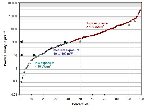
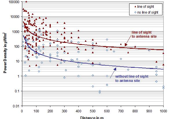
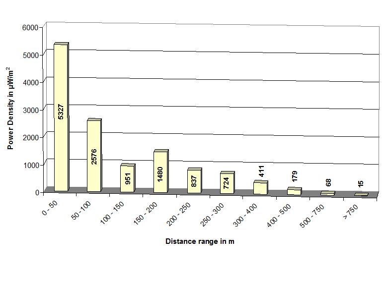
 This study presents data related to GSM (Global System for Mobile Communications) cellular phone radiation resulting from antenna sites and towers inside residential areas in Germany. A statistical evaluation of over 200 representative high frequency field measurements is presented for the years 2001 and 2002.
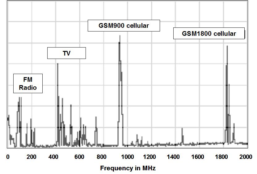
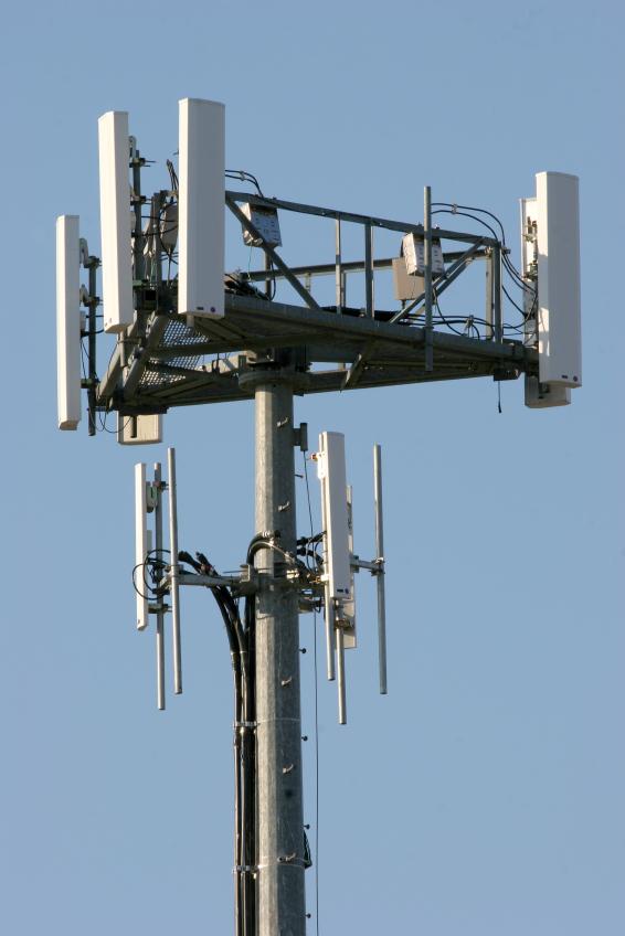 The objective of this field study was to collect measurement data, statistical evaluation, documentation and exposure assessment for cellular phone tower radiation in Germany. Measurements were conducted at different distances and directions, inside and outside of representative public and residential buildings. Frequency selective spectrum analysis was used to obtain GSM power densities following the current recommendations for GSM cellular phone radiation measurements.
 One (1) hertz is one repetition of the sinusoidal wave per second. The frequency (f) is the frequency in hertz (Hz), meaning the number of cycles per second. One hertz simply means “one cycle per second”. 100Hz means “one hundred cycles per second”. The power line frequency is the frequency of the oscillations of alternating current (AC) in an electric power grid transmitted from a power plant to the end-user.
 Conductors are wires which transport the electrical current. Electrical power systems generate magnetic and electric fields extending from the conductors. Magnetic fields are produced by the current flow in a conductor. Electric fields are produced by the voltage present on a conductor even without a current flow. The AC magnetic field is scientifically referred to as the magnetic flux density and is measured in units of milliGauss (mG) in the United States and in Tesla (T) in Europe. Electric fields are measured in units of Volts per meter (V/m).
 Magnetic fields are relatively easily measured with direct reading instruments. Magnetic fields extend in a quasi concentric circular pattern from the conductor (wire). Electric fields are significantly more difficult to measure. The field emitted from the source wants to reach the ground. The person conducting the measurements becomes part of this pathway and alters the electric field lines and results.
 The terms “line” and “point” sources are used to define the sources for the magnetic fields. Line sources are transmission and distribution lines, electrical feeders and internal building wiring systems. Point sources are electrical transformers and motors. In a point source the conductors (wires) are wound up to create a coil.
 Coils are used to measure the magnetic flux density. The magnetic field induces a current flow in the coil which is measured and calibrated to express the magnetic field strength. Since magnetic fields are directional, the coil needs to be oriented in space so that the magnetic field lines flow through the center of the coil. An instrument with a single coil is referred to as a single axis meter. It needs to be oriented around the x, y and z axis in space to obtain the maximum field strength reading. This can be cumbersome and time consuming. Therefore, today’s professional instruments contain three coils to measure the three axes at the same time and provide a measurement result without having to rotate the instrument. Single axis measurements are the tool of choice when trying to determine the EMF source. A professional instrument with a 3 axis sensor array should also have linear frequency response. That means that the
  This calculation is performed electronically internal inside the instrument. Consumer instruments may not have a linear frequency response, resulting in erroneous results when other 60 Hz frequency fields are present.
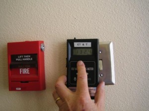 High field out light switch
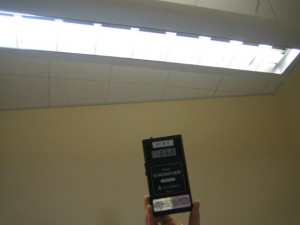 Elevated field at ceiling light
 High field next to an air filtration device
 Service drops will create high field on opposing wall
 Electrical transmission lines create magnetic fields due to current flow and electric fields due to the voltage present. Power lines usually create relatively high magnetic field levels. This is related to the fact that the conductors (wires) are separated by large distances and therefore largely eliminating the cancelation effect of opposite and equal forces. Furthermore, large current flow contributes to the large magnetic flux density.
 Utility transmission lines carry three (3) electrical conductors (wires) for each circuit. Therefore, it is referred to as a 3-phase circuit. The configuration of the individual conductors on the towers has a significant effect on the strength of the resulting magnetic field.
 1979, serious research about
  In 1992, Congress, as a part of the Energy Policy Act of 1992, mandated a $65 million, five year study to determine if exposure to low level, low frequency electromagnetic fields is detrimental to health and if so, to provide an assessment of risk. This full funding was never forthcoming. The Department of Energy (DOE) and the National Institute of Environmental Health Sciences (NIEHS) were charged with directing this research. Most of the work is known as the Research and Public Information Dissemination (RAPID) Program.
 In 1993, the California Public Utilities Commission (CPUC) Decision 93-11-013 created the